BC Robotics
Browse categories
- New Additions
- Shop
- On Sale / Clearance
- Popular Categories
- ArduinoArduino is the most popular open source microcontroller platform on the market. These easy to program devices can read sensors, control relays, light up LEDs, and even talk to one another. Their ability to interact with the real world by way of sensors and other electronics makes them ideal for automation such as watering a plant when it is dry, reading the weather, or controlling lights when it gets dark – the possibilities are endless. We carry a variety of Arduino compatible microcontrollers from several manufacturers, each with their own specific strengths and purposes. To further specialize your microcontroller, we carry a large selection of daughter boards (shields) which can add powerful sensors, GPS, or even LCD screens to your project! Just getting started with microcontrollers? We carry a variety of Arduino starter kits to get you reading sensors and blinking lights as easily as quickly as possible!
- BBC micro:bitThe BBC micro:bit is a pocket-sized computer designed for beginners in electronics and coding. The micro:bit makes getting into these often daunting fields as easy as possible. Programming the micro:bit V2 can be done by computer or by their intuitive app available for Android and iOS devices. Code can be designed using a drag and drop interface in the Blocks editor, Javascript, or Python.
- ESP8266 & ESP32The ESP8266 and ESP32 microcontrollers from Espressif are powerful, inexpensive, and feature integrated WiFi connectivity. These are ideal for IoT applications. We offer a variety of different ESP8266 and ESP32 modules for different skill levels.
- FeatherFeather is a flexible and powerful family of microcontroller main-boards (Feathers) and daughter-boards (Wings) designed with portability in mind. All Feathers have integrated battery connectors (and most have built in lipo chargers) The Feather form factor is not locked to a specific chipset or programming language. Feathers are available with a variety of chipsets and on-board features. Most Feathers and FeatherWings have example code and libraries written in Arduino C/C++ and CircuitPython.
- Makey MakeyThe Makey Makey kit is a electronics kit designed for beginners. It explores the concepts of creating circuits through everyday items. When plugged into a computer you can use the Makey Makey to make anything into a keyboard or mouse. No programming required! Projects like a Banana Drum Set, Cat Detector, Musical Stairs, and countless others are easier than you think! We carry the Makey Makey Classic Kit – a starter kit for the Makey Makey – along with extra alligator clips, copper conductive tape, and replacement cables.
- Raspberry PiThe Raspberry Pi was first introduced in early 2012 as a simple, low cost, computer fit onto a circuit board roughly the size of a credit card. The idea was to use this low cost computer to promote teaching of computer science in schools but it has grown to be so much more! Since its release, well over 30 million of these little computers have been sold. We have carried the Raspberry Pi in Canada since it first became available and have watched as the Pi has morphed into a complete development platform with powerful single-board computers, cameras, touchscreens, and other accessories. Its multitude of inputs and outputs for electronics and computer peripherals and its impressive computing power mean it can be used to make just about anything you can imagine. The newest and most powerful version, the Raspberry Pi 4, is now available!
- Popular Brands
- AdafruitAdafruit was founded in 2005 by MIT engineer, Limor “Ladyada” Fried. Her goal was to create the best place online for learning electronics and making the best designed products for makers of all ages and skill levels. In the last 10 years, Adafruit has grown to over 100+ employees in the heart of NYC with a 50,000+ sq ft. factory.
- ArduinoArduino is an ever growing platform used by some of the most popular microcontrollers out there. For many of us, this is where it all started – the Arduino was (and still is today) a pioneer when it comes to making programming hardware easy and accessible. We have one of the largest selections of Arduino and Arduino accessories in Canada. These range from basic Arduino Uno, to Cellular and WiFi connected devices perfect for the Internet of Things, and all the accessories needed to get them running!
- Micro:bitMicro:bit Educational Foundation are the manufacturers of the popular BBC micro:bit; a pocket-sized computer designed for beginners in electronics and coding. The micro:bit makes getting into these often daunting fields as easy as possible. Programming the micro:bit V2 can be done by computer or by their intuitive app available for Android and iOS devices. Code can be designed using a drag and drop interface in the Blocks editor, Javascript, or Python.
- BC RoboticsIn addition to stocking 2000+ unique items, we also manufacture our own accessories right here at BC Robotics. In 2014 we began developing our own widgets and add-ons for Arduino, Raspberry Pi, and general prototyping. This has now grown to over 80 different SKUs. Our boards are assembled in-house with top quality components. Many feature detailed tutorials or project guides to get you up and running as quickly as possible!
- Raspberry Pi
- SparkFunSince 2003, SparkFun has been helping turn ideas into reality – whether you’re creating a smart weather station, exploring the frontier of machine learning, building a robot for school or prototyping your first (or tenth) product. No matter your vision or skill level, our open source components, resources and online tutorials are designed to broaden access to innovative technology and make the road to a finished project shorter. We’re here to help you start something.
- Frequently Asked Questions
- My Account
- Wishlist
- Cart
Free Shipping - US & Canada @ $150 CAD
Using an Ultrasonic Distance Sensor With Arduino
PRODUCT TUTORIAL
- Chris @ BCR
- November 8, 2018
- 12:54 pm
- One Comment
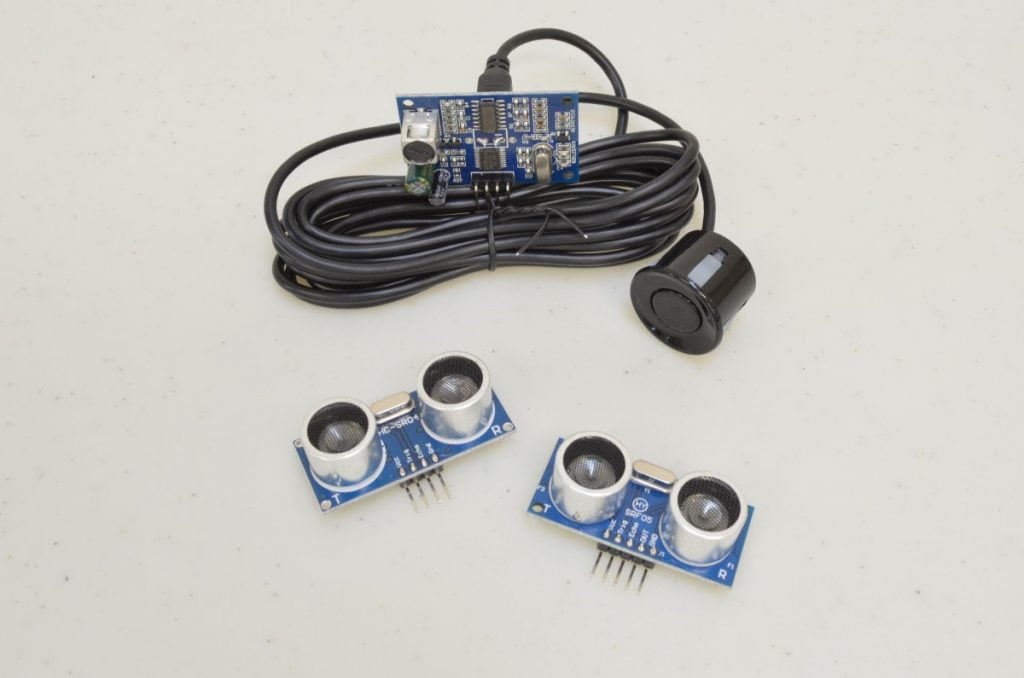
In this tutorial we will be looking at how to use an Ultrasonic Sensor to measure distance using an Arduino. This type of sensor emits a burst of ultrasonic sound and then waits to hear the echo. These sensors are generally inexpensive, fairly accurate, and not affected by lighting conditions like infrared based systems. We will be looking at three sensors, these are all code compatible but require subtle changes in the wiring due to differing pinouts.
A Few Considerations:
Before we jump into getting this sensor hooked up there are a few points to consider when using it in a project.
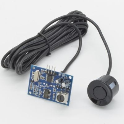
• If there is any chance of these coming in contact with water, the weatherproof version must be used.
• The further an object is away, the larger it needs to be to have reliable detection.
How It Works:
The sensor itself takes care of most of the heavy lifting and as a result, there is one input (Trigger) and one output (Echo). When the trigger is set high, an ultrasonic burst is sent and the circuit internal to the sensor starts watching for a response. When the response is received, the echo pin is immediately triggered high. We can simply time how long it takes from trigger to echo and divide by two. Since sound travels at a reasonably consistent speed, the distance is easy to obtain.
The Parts Needed:
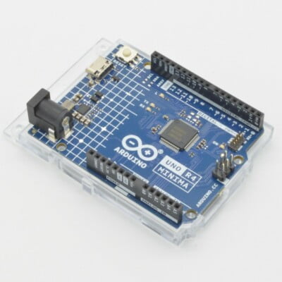
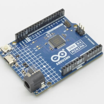
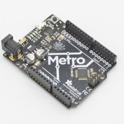
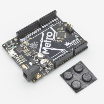
In this tutorial we are using an Arduino Uno, however any R3 compatible boards should work:
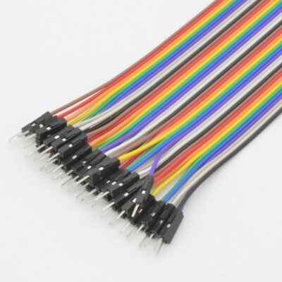
View cart “Premium Male/Male Jumper Wires – 12″” has been added to your cart.
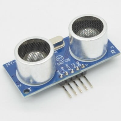
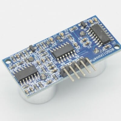
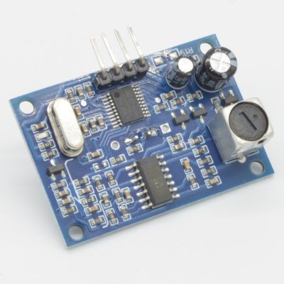
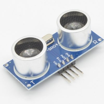
An ultrasonic sensor will also be required, we based the tutorial on the HC-SR04 , but any of the following will work. Just be sure to watch the pinouts!
Finally, we will need a few other components and prototyping parts to hook it all up:

The Schematic
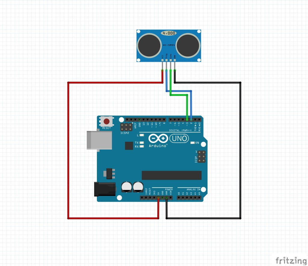
This handy little diagram shows how we will be connecting everything. Depending on the sensor, the pinout may vary slightly. Don’t worry if it looks a little overwhelming, we will be going through this step by step!
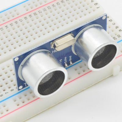
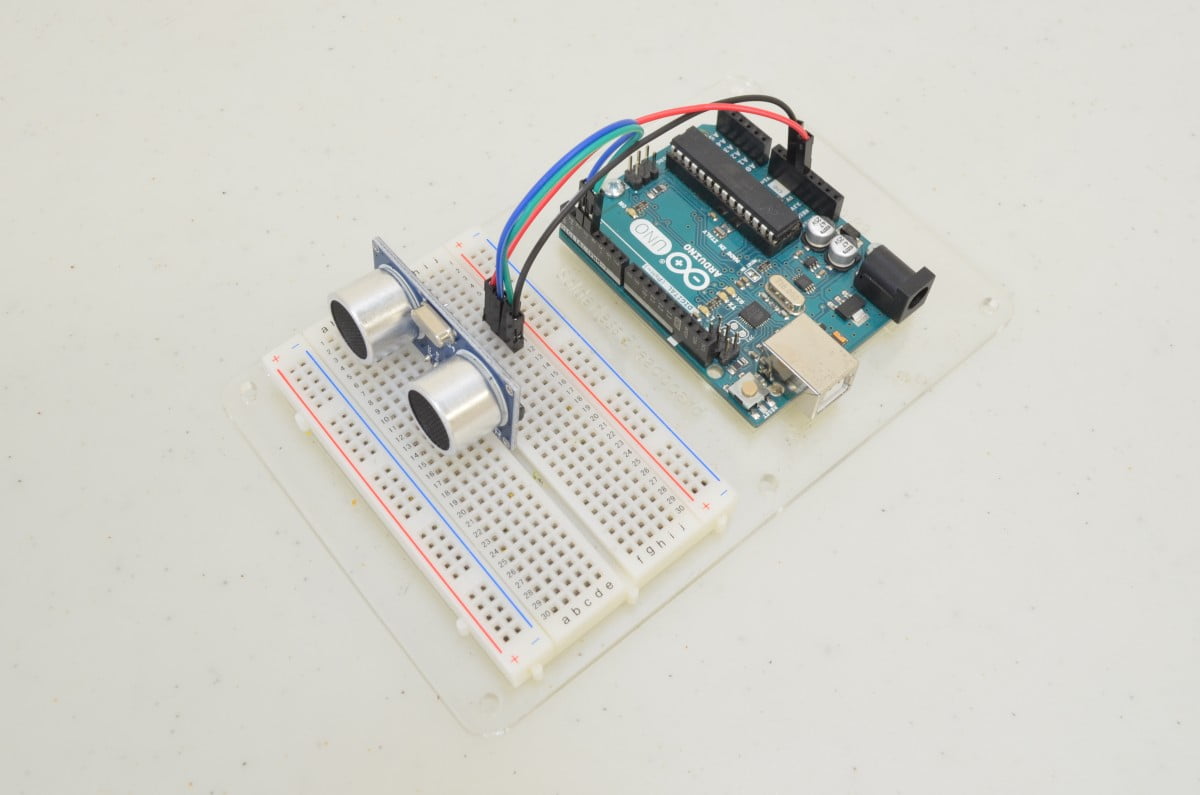
Step 1 – Wire Up The Sensor
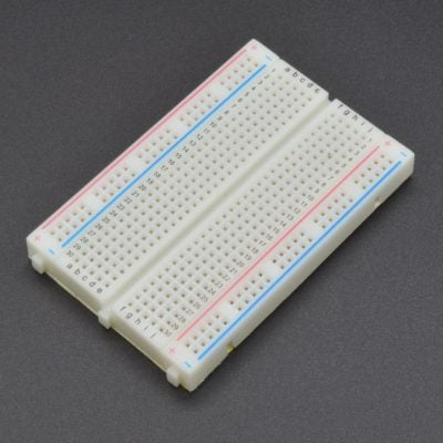
These sensors typically have breadboard compatible pins so we can simply insert it into the breadboard as shown. While the pin layout of each sensor will vary, the pins are labeled directly on the board – so hookup is a breeze. VCC will go to our 5V rail on the breadboard, GND will go to the Ground rail. We will run TRIG directly to digital pin 2 on the Arduino and run ECHO directly to digital pin 3.
Note: If you are using the HY-SRF05, there is an extra “OUT” pin in the header. This pin can simply be left disconnected.
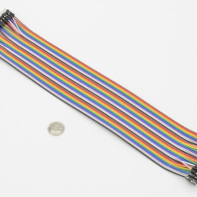
Note: If you don’t have a breadboard, you can just as easily connect this sensor directly to the Arduino pins as well. Just use our Premium Female/Male Jumper Wires to connect them instead.
0%
Step 2 – Double Check And Plug It In!
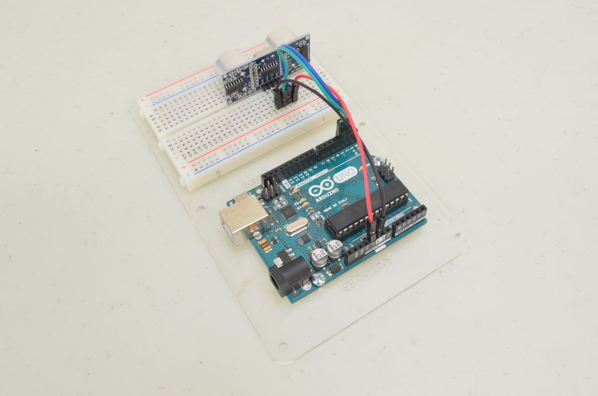
Before we give the Arduino power it is always a good idea to go over all of the connections to make sure there are no wires in the wrong spot – sometimes that can make for a very expensive mistake!
One way to avoid this problem is good wire color discipline. In other words, decide on a purpose for each color of wire and stick to them! In this example all 5V power are red wires, all grounds are black wires, and green / blue / ect. are signal wires. This way, if you ever see a red wire going to a black wire you will know right away that something isn’t quite right!
10%
Step 3 - Starting The Code
					void setup() {
// put your setup code here, to run once:
}
void loop() {
// put your main code here, to run repeatedly:
}
Now that we have finished with the hookup we need to start writing some code. We will be using the Arduino IDE, this is available from https://www.arduino.cc/en/Main/Software
We will start with the “BareMinimum” sketch found by clicking “File” and selecting Examples / Basic / BareMinimum. This sketch is a great starting point as it includes the Setup and Loop functions – we will write the rest!
20%
Step 4 – Understanding How To Read The Sensor
We know that if we set the trigger pin high an ultrasonic burst will be sent, and once the echo is detected, the echo pin will be triggered high. So this is really just a matter of timing how long it takes the sound to bounce back and dividing by two. We can then use that to figure out the distance by dividing by the speed of sound.
There are a lot of different ways this could be accomplished – in this case we will use the PulseIn function as it is relatively simple. This is normally used to measure frequency, but since the receiver will “hear” the output twice (initially when it is sent, and the echo off the objec) we can use this to count the time between send and receive.
30%
Step 5 – Starting The Code
We are starting with the BareMinimum Sketch found in the IDE, it should look something like this:
					void setup() {
// put your setup code here, to run once:
}
void loop() {
// put your main code here, to run repeatedly:
}
The Setup section is used for anything that needs to be done once when the Arduino starts. The Loop section will be run over and over again in a loop.
40%
Step 6 – Define Constants
We are going to start by defining what pin we are going to use for our trigger and echo. These are the pins on the Arduino that you have connected the TRIG and ECHO pins on the sensor. We then configure the TRIG pin as an output and the ECHO as an input. A good way to remember how this works: When ever you are “telling” a piece of electronics to do something using the Arduino it will be an OUTPUT; if you are “listening” to something, it would be an INPUT.
					//Define our pins
#define TRIG 2 //Define the Trigger Pin
#define ECHO 3 //Define the Echo Pin

void setup() {
// put your setup code here, to run once:
    pinMode(TRIG, OUTPUT); //Configure Trigger as an Output (to send a signal)
    pinMode(ECHO, INPUT); //Configure Echo as an Input (to receive a signal)
}
void loop() {
// put your main code here, to run repeatedly:

}
50%
Step 7 – Setup Serial
We need some way to display the sensor data – in this case the Serial Monitor built into the Arduino IDE is probably the easiest. The serial monitor allows data collected or calculated by the Arduino to be displayed on the computer you are programming the Arduino from. The serial connection is configured in the Setup function:
					//Define our pins
#define TRIG 2 //Define the Trigger Pin
#define ECHO 3 //Define the Echo Pin

void setup() {
// put your setup code here, to run once:
    pinMode(TRIG, OUTPUT); //Configure Trigger as an Output (to send a signal)
    pinMode(ECHO, INPUT); //Configure Echo as an Input (to receive a signal)
    Serial.begin(9600); //Start Serial Connection @ 9600 Baud Rate
}
void loop() {
// put your main code here, to run repeatedly:

}
60%
Step 8 – Triggering The Sensor
The first step in measuring a distance is triggering the sensor to send the ultrasonic pulse. This is done by setting the TRIG pin HIGH for 10 microseconds.
					//Define our pins
#define TRIG 2 //Define the Trigger Pin
#define ECHO 3 //Define the Echo Pin

void setup() {
// put your setup code here, to run once:
    pinMode(TRIG, OUTPUT); //Configure Trigger as an Output (to send a signal)
    pinMode(ECHO, INPUT); //Configure Echo as an Input (to receive a signal)
    Serial.begin(9600); //Start Serial Connection @ 9600 Baud Rate
}
void loop() {
// put your main code here, to run repeatedly:
    digitalWrite(TRIG, HIGH);//Set TRIG pin HIGH
    delayMicroseconds(10); //Pause 10 microseconds
    digitalWrite(TRIG, LOW); //Set TRIG pin LOW
}
70%
Step 9 – Listening For The Echo
Next we will listen for the echo – this means we need to use the PulseIn function with our ECHO pin. Since the sensor outputs a HIGH signal when triggered, we will be looking to count time between HIGH pulses.
The PulseIn function returns a time in microseconds, and since sound travels at approximately 29cm / microsecond, we can figure out a distance. The distance returned would be the distance the sound traveled (to the object and back), so we will have to also divide the distance by two: returnTime / 29 / 2 (or returnTime / 58 to simplify it)
					//Define our pins
#define TRIG 2 //Define the Trigger Pin
#define ECHO 3 //Define the Echo Pin

void setup() {
// put your setup code here, to run once:
    pinMode(TRIG, OUTPUT); //Configure Trigger as an Output (to send a signal)
    pinMode(ECHO, INPUT); //Configure Echo as an Input (to receive a signal)
    Serial.begin(9600); //Start Serial Connection @ 9600 Baud Rate
}
void loop() {
// put your main code here, to run repeatedly:
    digitalWrite(TRIG, HIGH);//Set TRIG pin HIGH
    delayMicroseconds(10); //Pause 10 microseconds
    digitalWrite(TRIG, LOW); //Set TRIG pin LOW

    float distance = pulseIn(ECHO, HIGH); //ECHO Pin, Looking for a HIGH signal
    distance = distance / 58; //Time in microseconds divided by twice the distance sound travels per microsecond (cm)
}
80%
Step 10 – Print The Results
Finally, we will want to see the results. To do this, we will print the value to the serial monitor. We will also add a small delay so we aren’t overloaded with information.
					//Define our pins
#define TRIG 2 //Define the Trigger Pin
#define ECHO 3 //Define the Echo Pin

void setup() {
// put your setup code here, to run once:
    pinMode(TRIG, OUTPUT); //Configure Trigger as an Output (to send a signal)
    pinMode(ECHO, INPUT); //Configure Echo as an Input (to receive a signal)
    Serial.begin(9600); //Start Serial Connection @ 9600 Baud Rate
}
void loop() {
// put your main code here, to run repeatedly:
    digitalWrite(TRIG, HIGH);//Set TRIG pin HIGH
    delayMicroseconds(10); //Pause 10 microseconds
    digitalWrite(TRIG, LOW); //Set TRIG pin LOW

    float distance = pulseIn(ECHO, HIGH); //ECHO Pin, Looking for a HIGH signal
    distance = distance / 58; //Time in microseconds divided by twice the distance sound travels per microsecond (cm)

    Serial.print(distance); //Print the distance to the serial monitor
    Serial.println(" cm"); //Add the unit of measure to the end of the line
    delay(500); //Delay for half a second so we dont overload the serial port
}
90%
Step 11 – Upload The Code And Test
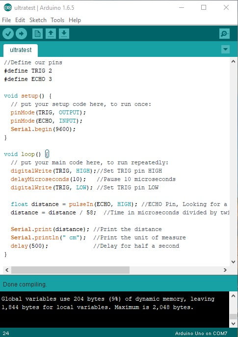
Now that all of the code has been written it can be uploaded to your Arduino! Click “Upload” button in the top left corner of the Arduino IDE and it should upload without any issues.
Next, click the “Serial Monitor” button in the top right corner (it looks like a magnifying glass). This will open a new window. After a few seconds you should start to see a stream of data appear in the window – that is your distance in centimeters.
100%
One thought on “Using an Ultrasonic Distance Sensor With Arduino”
Jonathan
Would it be possible to have 3-6 sensors triggering an Arduino simultaneously? For instance if I wanted to use these to get 360ish degrees of coverage? thanks in advance!