BC Robotics

Browse categories
- New Additions
- Shop
- On Sale / Clearance
- Popular Categories
- ArduinoArduino is the most popular open source microcontroller platform on the market. These easy to program devices can read sensors, control relays, light up LEDs, and even talk to one another. Their ability to interact with the real world by way of sensors and other electronics makes them ideal for automation such as watering a plant when it is dry, reading the weather, or controlling lights when it gets dark – the possibilities are endless. We carry a variety of Arduino compatible microcontrollers from several manufacturers, each with their own specific strengths and purposes. To further specialize your microcontroller, we carry a large selection of daughter boards (shields) which can add powerful sensors, GPS, or even LCD screens to your project! Just getting started with microcontrollers? We carry a variety of Arduino starter kits to get you reading sensors and blinking lights as easily as quickly as possible!
- BBC micro:bitThe BBC micro:bit is a pocket-sized computer designed for beginners in electronics and coding. The micro:bit makes getting into these often daunting fields as easy as possible. Programming the micro:bit V2 can be done by computer or by their intuitive app available for Android and iOS devices. Code can be designed using a drag and drop interface in the Blocks editor, Javascript, or Python.
- ESP8266 & ESP32The ESP8266 and ESP32 microcontrollers from Espressif are powerful, inexpensive, and feature integrated WiFi connectivity. These are ideal for IoT applications. We offer a variety of different ESP8266 and ESP32 modules for different skill levels.
- FeatherFeather is a flexible and powerful family of microcontroller main-boards (Feathers) and daughter-boards (Wings) designed with portability in mind. All Feathers have integrated battery connectors (and most have built in lipo chargers) The Feather form factor is not locked to a specific chipset or programming language. Feathers are available with a variety of chipsets and on-board features. Most Feathers and FeatherWings have example code and libraries written in Arduino C/C++ and CircuitPython.
- Makey MakeyThe Makey Makey kit is a electronics kit designed for beginners. It explores the concepts of creating circuits through everyday items. When plugged into a computer you can use the Makey Makey to make anything into a keyboard or mouse. No programming required! Projects like a Banana Drum Set, Cat Detector, Musical Stairs, and countless others are easier than you think! We carry the Makey Makey Classic Kit – a starter kit for the Makey Makey – along with extra alligator clips, copper conductive tape, and replacement cables.
- Raspberry PiThe Raspberry Pi was first introduced in early 2012 as a simple, low cost, computer fit onto a circuit board roughly the size of a credit card. The idea was to use this low cost computer to promote teaching of computer science in schools but it has grown to be so much more! Since its release, well over 30 million of these little computers have been sold. We have carried the Raspberry Pi in Canada since it first became available and have watched as the Pi has morphed into a complete development platform with powerful single-board computers, cameras, touchscreens, and other accessories. Its multitude of inputs and outputs for electronics and computer peripherals and its impressive computing power mean it can be used to make just about anything you can imagine. The newest and most powerful version, the Raspberry Pi 4, is now available!
- Popular Brands
- AdafruitAdafruit was founded in 2005 by MIT engineer, Limor “Ladyada” Fried. Her goal was to create the best place online for learning electronics and making the best designed products for makers of all ages and skill levels. In the last 10 years, Adafruit has grown to over 100+ employees in the heart of NYC with a 50,000+ sq ft. factory.
- ArduinoArduino is an ever growing platform used by some of the most popular microcontrollers out there. For many of us, this is where it all started – the Arduino was (and still is today) a pioneer when it comes to making programming hardware easy and accessible. We have one of the largest selections of Arduino and Arduino accessories in Canada. These range from basic Arduino Uno, to Cellular and WiFi connected devices perfect for the Internet of Things, and all the accessories needed to get them running!
- Micro:bitMicro:bit Educational Foundation are the manufacturers of the popular BBC micro:bit; a pocket-sized computer designed for beginners in electronics and coding. The micro:bit makes getting into these often daunting fields as easy as possible. Programming the micro:bit V2 can be done by computer or by their intuitive app available for Android and iOS devices. Code can be designed using a drag and drop interface in the Blocks editor, Javascript, or Python.
- BC RoboticsIn addition to stocking 2000+ unique items, we also manufacture our own accessories right here at BC Robotics. In 2014 we began developing our own widgets and add-ons for Arduino, Raspberry Pi, and general prototyping. This has now grown to over 80 different SKUs. Our boards are assembled in-house with top quality components. Many feature detailed tutorials or project guides to get you up and running as quickly as possible!
- Raspberry Pi
- SparkFunSince 2003, SparkFun has been helping turn ideas into reality – whether you’re creating a smart weather station, exploring the frontier of machine learning, building a robot for school or prototyping your first (or tenth) product. No matter your vision or skill level, our open source components, resources and online tutorials are designed to broaden access to innovative technology and make the road to a finished project shorter. We’re here to help you start something.
- Frequently Asked Questions
- My Account
- Wishlist
- Cart
Free Shipping - US & Canada @ $150 CAD
Getting Started With The Raspberry Pi Relay HAT
PRODUCT TUTORIAL
- Chris @ BCR
- October 18, 2018
- 5:17 pm
- 7 Comments
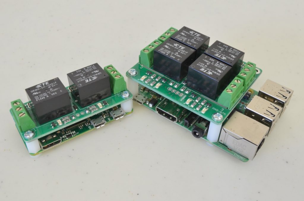
Our Pi Relay HATs are designed to allow your Pi to switch higher voltages and higher currents from one self contained board. In this tutorial we are going to go over soldering the header to the Relay HAT, use Python with the included Pi.GPIO library to write code that triggers each relay, and go over the external relay connections and configuration options on the board.
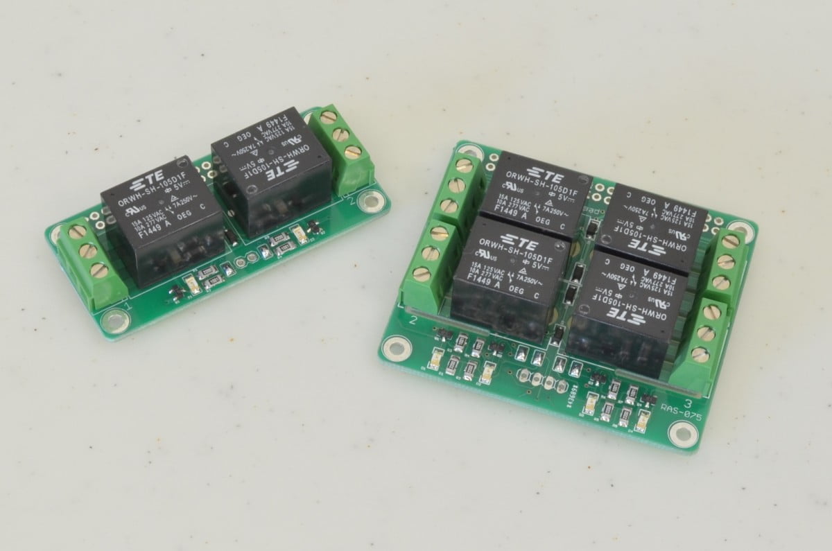
We make four versions of this relay board, two for the standard Raspberry Pi with 4 relays, and two for the Raspberry Pi Zero with 2 relays, with one fully assembled version and one without headers for each. On the board, each relay’s Common, Normally Open, and Normally Closed pins are brought out to screw terminals. These are not the most sophisticated circuits, but they do provide a compact, permanent solution for attaching a number of relays to the Pi.
This tutorial can be used for all versions of our Raspberry Pi Relay HATs:
- Raspberry Pi 4 Channel Relay HAT
- Raspberry Pi 4 Channel Relay HAT – Assembled
- Raspberry Pi Zero Relay HAT
- Raspberry Pi Zero Relay HAT – Assembled
The code for controlling the relays is also applicable to both versions of our Raspberry Pi Power Relay HATs:
Safety Note:
The boards are designed to handle higher voltages, but we do not recommend doing so for anyone unfamiliar with the dangers of high voltage. If you are inexperienced or unsure about how to use this product safely we recommend looking at the IoT Power Relay, which has all of its high voltage circuitry fully enclosed
Recommended Parts & Compatibility
Compatibility:
- 4 Channel Relay HATs are compatible with all versions of the Raspberry Pi A+ and B+ onwards. This includes the Raspberry Pi A+, 3A+, B+, 2, 3, 3+, and all versions of the Raspberry Pi 4.
- Zero Relay HATs are compatible with all versions of the Raspberry Pi Zero.
Please Note:
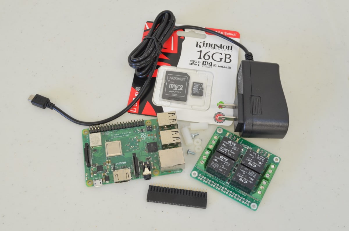
Depending on which board you are working with, the instructions and accessories required will vary slightly.
- 1 x Raspberry Pi
- 1 x microSD card (with Raspbian 2018-06-27 or newer)
- 1 x Raspberry Pi Power Supply
- 1 x Raspberry Pi 4 Channel Relay HAT
- 1 x Raspberry Pi Tall Header
- 2 x 4/40 x 5/8″ Standoff Nylon
- 2 x 4/40 x 1/4″ Screw
- 2 x 4/40 Nut – Nylon
- 1 x Raspberry Pi
- 1 x microSD card (with Raspbian 2018-06-27 or newer)
- 1 x Raspberry Pi Power Supply
- 1 x Raspberry Pi 4 Channel Relay HAT
- 1 x Raspberry Pi HAT Hardware – 1/2″
- 1 x Raspberry Pi Zero
- 1 x microSD card (with Raspbian 2018-06-27 or newer)
- 1 x Raspberry Pi Power Supply
- 1 x Raspberry Pi Zero Relay HAT
- 1 x Raspberry Pi GPIO Header
- 1 x Raspberry Pi 2×20 Pin Breakaway Male Header
- 1 x Raspberry Pi HAT Hardware
- 1 x Raspberry Pi Zero
- 1 x microSD card (with Raspbian 2018-06-27 or newer)
- 1 x Raspberry Pi Power Supply
- 1 x Raspberry Pi Zero Relay HAT – Assembled
- 1 x Raspberry Pi 2×20 Pin Breakaway Male Header
- 1 x Raspberry Pi HAT Hardware – 1/2″
0%
Step 1 - A Quick Overview
There isn’t much in the way of assembly required with these boards. For those versions without a header, one will need to be soldered in. For versions with the header already installed, feel free to jump to Step 5.
Header Selection: For all standard Raspberry Pi we recommend using a Tall Header, as this will allow inputs on the “USB / Ethernet” side of the Pi to clear. For the Pi Zero, a shorter header can be used so we recommend using the standard GPIO header, but feel free to go a different way as needed. Once we have the headers soldered in, we will use Python and the GPIO library to write some code to trigger each relay, and finally we will look at the different connections on the board.
7.7%
Step 2 – Soldering The Header
We are going to recycle a couple old photos in the next two steps for soldering the header. The boards are different, but the overall process is the same.
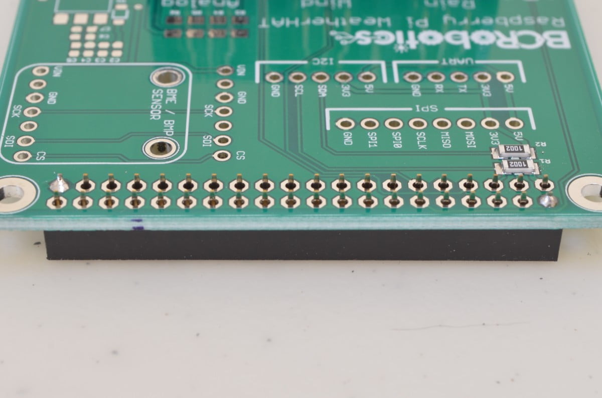
First we need to solder the header that allows this board to plug into the Raspberry Pi. If you haven’t soldered before, or want a quick refresher course, have a look at this awesome comic: Soldering Is Easy! https://mightyohm.com/…/FullSolderComic_EN.pdf
Start by Tacking two opposite corners of the connector in place and checking the connector alignment. We do this to ensure the connector is sitting correctly before soldering all 40 pins; once these have all been soldered, it is very difficult to adjust the alignment.
15.3%
Step 3 – Soldering the header (continued)
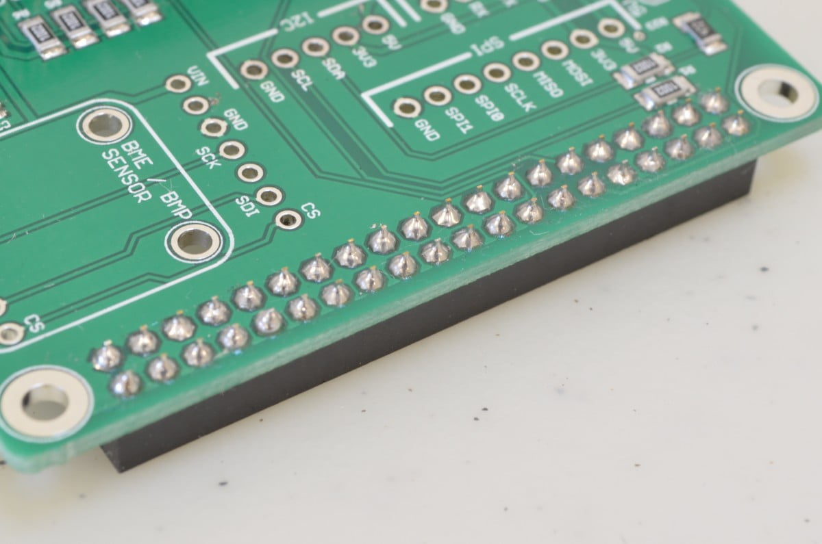
Once the connector is aligned to the board, and you are happy with the alignment, solder the remaining pins. It should look something like the attached photo when you are finished (but with relays and such!)
23%
Step 4 – Double Check Your Work!
Before we power anything up, it is always a good idea to go through and make sure there are no issues with the work that has been done. Make sure all the solder joints are clean, with no un-intended bridging. Once the board has been checked over, install it on top of the Pi.
30.7%
Step 5 – HAT Hardware

When using HATs with the Raspberry Pi, we recommend some form of standoff hardware to keep everything firmly connected. In this tutorial, depending on whether you are using an assembled board or one with headers of your choice.
- For the Pi Zero, using the GPIO header we recommend using the Raspberry Pi HAT Hardware Kit.
- When using the tall header (as we did with the standard Pi) you will need something quite a bit taller. We recommend going to the 5/8” Nylon Standoffs with 4/40 Nylon Nuts and 4/40 x 1/4″ Screws.
- For Assembled versions we recommend the Raspberry Pi HAT Hardware – 1/2″ kit.
38.4%
Step 6 – Getting Ready To Power Up Your Pi
Before we get the Pi powered up, you should have a microSD card pre-installed with Raspbian. We are using the installation image dated June 27, 2018 but any version newer than that should work just as well.
Once this has been completed, we are going to insert the microSD card into the Pi. Your keyboard, mouse and monitor should also be connected at this time. Power up the Pi by plugging in the Power Supply. Once the Pi has done its initial boot of the operating system you should arrive at a desktop. A dialogue should appear for initial configuration – follow through the steps as instructed.
46.1%
Step 7 – Controlling The HAT
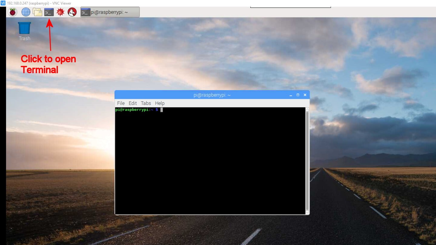
Conveniently, the software library we need is included in the default Raspbian image. We won’t need to do much configuration in this tutorial to control the HAT! While this tutorial is using Python 2.7 , this code can be used in Python 3 as well – luckily the code is cross compatible. Click the terminal logo up top and type “Idle”
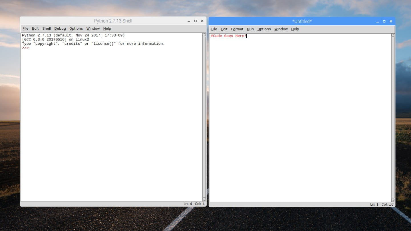
A new window should have opened for the Python 2.7 / Python 3 Shell. We are now done with the terminal window so it can be minimized or moved out of the way (but don’t close it!).
53.8%
Step 8 – Write some of our own code
In the Python Shell window we just opened, click “File” and “New File” to start a new Python file. This will open another window that we will write all of our code in. We aren’t going to write anything too complicated – just a simple program to turn each relay on and off. This code can then be used going forwards to work the Relay HAT into your project!
61.5%
Step 9 – Starting The Code
					import time

interval = 1 #How long we want to wait (seconds)

while True:
    time.sleep(interval)
Before we can trigger any of the relays, we will need to create the basic framework of the program. This means we need to import the time library, create our loop, and set the interval we want to pause the code. In this instance we are going to pause between each relay trigger event. For those unfamiliar with Python, note that the white spaces (tabs and spaces) are very important in this language so be sure to format exactly as shown in the example.
Libraries are added to the project using the import command. On the first line we are importing the time library. On line 3 we define a variable to store the length of time in seconds that we want to sleep the program during each loop of the code. Next, we want to create the loop itself – in Python this can be done in a variety of ways; “While true:” works well. Note that when you press “Enter” the next line becomes indented. Finally, on line 6 we “sleep” or pause our program using the variable we set above. The end result is a program that starts, and then runs whatever code we stick in the loop once a second.
Note: Because we are going to be adding code over the next few steps, each new line we add will be highlighted in the example code and the line number will correspond to notes below the code.
69.2%
Step 10 – Import the libraries
					import time
import RPi.GPIO as GPIO

interval = 1 #How long we want to wait (seconds)

while True:
    time.sleep(interval)
- (2) import the GPIO library
We are now going to import the Raspberry Pi GPIO library. This is done the same way as we imported the time library.
76.9%
Step 11 – Configure GPIO
					import time
import RPi.GPIO as GPIO

GPIO.setmode(GPIO.BCM) # Broadcom pin-numbering scheme
GPIO.setup(4, GPIO.OUT) #set Relay 1 output
GPIO.setup(17, GPIO.OUT) #set Relay 2 output

#Pi Zero users do not need to configure the pins for Relays 3 & 4, these are unused.
GPIO.setup(27, GPIO.OUT) #set Relay 3 output
GPIO.setup(22, GPIO.OUT) #set Relay 4 output

interval = 1 # How long we want to wait (seconds)

while True:

time.sleep(interval)
- (4) Set to the Broadcom pin-numbering scheme so the correct pins are triggered
- (5-6) Set pins 4 and 17 as output pins (Relays 1 & 2)
- (9-10) Set pins 27 and 22 as output pins (Relays 3 & 4 , not used for Zero HAT)
We now need to configure the GPIO library and each of the pins we are using.
84.6%
Step 12 – Trigger a Relay
					import time
import RPi.GPIO as GPIO

GPIO.setmode(GPIO.BCM) # Broadcom pin-numbering scheme
GPIO.setup(4, GPIO.OUT) #set Relay 1 output
GPIO.setup(17, GPIO.OUT) #set Relay 2 output

#Pi Zero users do not need to configure the pins for Relays 3 & 4, these are unused.
GPIO.setup(27, GPIO.OUT) #set Relay 3 output
GPIO.setup(22, GPIO.OUT) #set Relay 4 output

interval = 1 # How long we want to wait (seconds)

while True:

GPIO.output(4, GPIO.HIGH) #turn relay 1 on
time.sleep(interval)
GPIO.output(4, GPIO.LOW) #turn relay 1 off
time.sleep(interval)
- (16) Set pin for relay 1 HIGH to turn on relay
- (17) Wait 1 second
- (18) Set pin for relay 1 LOW to turn off relay
With everything configured, we can now trigger relays on and off with a simple line of code.
Hit “F5” on the keyboard – this will prompt you to save the file. Once saved, the program should start running. As soon as the program starts, Relay 1 should begin clicking and the indicator LED for Relay 1 flashing on and off every second.
92.3%
Step 13 – Trigger The Remaining Relays
					import time
import RPi.GPIO as GPIO

GPIO.setmode(GPIO.BCM) # Broadcom pin-numbering scheme
GPIO.setup(4, GPIO.OUT) #set Relay 1 output
GPIO.setup(17, GPIO.OUT) #set Relay 2 output

#Pi Zero users do not need to configure the pins for Relays 3 & 4, these are unused.
GPIO.setup(27, GPIO.OUT) #set Relay 3 output
GPIO.setup(22, GPIO.OUT) #set Relay 4 output

interval = 1 # How long we want to wait (seconds)

while True:

GPIO.output(4, GPIO.HIGH) #turn relay 1 on
time.sleep(interval)
GPIO.output(4, GPIO.LOW) #turn relay 1 off
time.sleep(interval)

GPIO.output(17, GPIO.HIGH) #turn relay 2 on
time.sleep(interval)
GPIO.output(17, GPIO.LOW) #turn relay 2 off
time.sleep(interval)

#Not Used For Pi Zero
GPIO.output(27, GPIO.HIGH) #turn relay 3 on
time.sleep(interval)
GPIO.output(27, GPIO.LOW) #turn relay 3 off
time.sleep(interval)

#Not Used For Pi Zero
GPIO.output(22, GPIO.HIGH) #turn relay 4 on
time.sleep(interval)
GPIO.output(22, GPIO.LOW) #turn relay 4 off
time.sleep(interval)
- (21-24) Turn Relay 2 On and then Off
- (27-30) Turn Relay 3 On and then Off
- (33-36) Turn Relay 4 On and then Off
And now we can add the remaining relays using very similar code. Hit “F5” on the keyboard – save the file once again. This time when the program runs, each relay should cycle on and off in order.
Going forwards this code can be modified to use external triggers, sensor readings, etc. to control the relays as needed.
100%
Step 14 – External Connections
Now that we have everything working, how do the screw terminals for each of the relays work? They are fairly simple: these are Single Pole Dual Throw (SPDT) Relays, meaning they have a contact that is normally closed and a contact that is normally open. The third screw terminal connection is for a common pin. This configuration allows you to have circuits that are “Off” until the relay turns them on and circuits that are “On” until the relay turns them off.


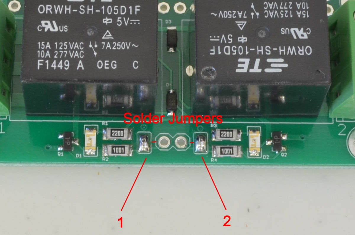
Step 15 – Using Other GPIO Pins (RAS-075 / RAS-109 Only)
On both header-less versions of the board we thought it might be useful to allow users to disconnect the default Raspberry Pi GPIO pins 7,11,13,15 (BCM numbers 4, 17, 22, 27) just in case they are needed for something else. Each relay has a solder jumper that will allow it to be disabled and a solder-able connection that could be connected to another GPIO pin. Alternatively, we do offer the same 4 Channel Relay circuit in an external breakout board that can be connected to any GPIO pin as well.

7 thoughts on “Getting Started With The Raspberry Pi Relay HAT”
John
I would encourage your followers of this tutorial to consider the Raspberry Pi Stacking Header for $3.95 to leave open the option of adding another hat such as the 16-channel Analog/Digital Converter for sensors such as a Moisture or Temperature Sensor. (Sensors/devices that output an analog signal.)
Even if another hat is not added, the stacking header provides easy access to the unused GPIO pins on the RaspberryPi for an expanded or future project.
Joe Goldthwaite
I’m using the PI Zero Relay HAT. For my use it might work better to mount it next to the PI instead of hooked up to the top and use jumper pins between the two.
I assume you’re using the power and ground pins. Are any of the other pins required for it to function?
Chris @ BCR
Pins used are GPIO 4 (Pin 7), GPIO 17 (Pin 11), 5V Power (Pin 2 or 4) and Ground (Pin 39)
casper
Is there a way to disable the indicator LED for Relays?
Chris @ BCR
Easiest way would be to remove all 4 resistors labeled “2200” – these are the current limiting resistors for the LEDs. Let us know if you have any further questions!
Wolfgang
Got PI Zero Relay HAT, but it looks different than the one in the tutorial and the header is already soldered. I don’t find any soldered jumper (Step 15); how can I change the GPIO-Pins??
William @ BC Robotics
Hi Wolfgang,
It sounds like you have the assembled version (RAS-194) of this board – the assembled version does not allow for the changing of IO pins as there would be no where to solder the needed jumper wires to in the header.