We always deal with electricity in our projects, but have you ever generated your own? This tutorial will step you through building our DIY Generator Kit. The DIY Generator is designed to light an LED purely by spinning a handle. Internally there is a gearbox to increase the rotation speed, and a simple DC Motor that acts as the generator. Spinning the included motor by hand wont generate a high enough voltage to light an LED, so this kit uses the gearbox to increase the rotational speed from the handle to the motor. This gives us a high enough voltage to brightly light an LED.
Please note: there are quite a few small parts here so be sure to keep them all together!
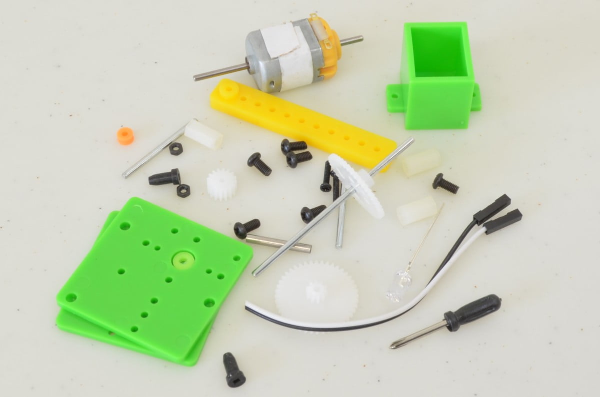
The Parts Needed:
The required parts for this tutorial aren’t too extensive:
[list type=”check”]
[/list]
Note: We do recommend soldering the LED to the motor leads, this would require a basic soldering kit and solder.
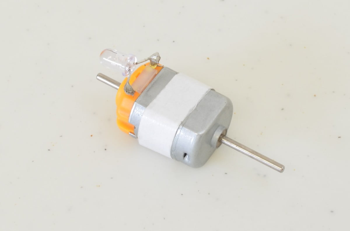
Step 1 – Get Everything Prepared
As mentioned above, we recommend soldering the LED to the motor leads. We find this makes it a lot easier to handle, and electrically much more reliable. The LED can be soldered in either orientation, just note that depending on which way the LED is soldered, determines which way you have to spin the handle to get the LED to light.
Step 2 – Insert the Motor
Next we are going to insert the motor into the motor holder. It should be a snug fit. Be sure to insert the motor so that the long shaft goes into the box, while the yellow end of the motor sticks out as shown in the photo.
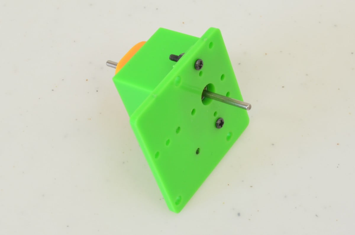
Step 3 – Attach the first Gearbox Panel
We now need to mount the motor to the first piece of the gearbox panel. To do this, we need the two small, long screws and their corresponding nuts. These will go through the panel and motor holder as shown in the second photo. Tighten them down using a Phillips screwdriver.
Step 4 – Attach the Motor Gear
The shaft itself isn’t really going to mesh well with the gearbox, so we need to attach a gear to the motor shaft. We are going to use the thick gear and press it onto the motor shaft. It is a fairly snug fit so be careful when pressing it on. Also, don’t press it on so far that it is tight against the gearbox panel, there should be gap between the two.
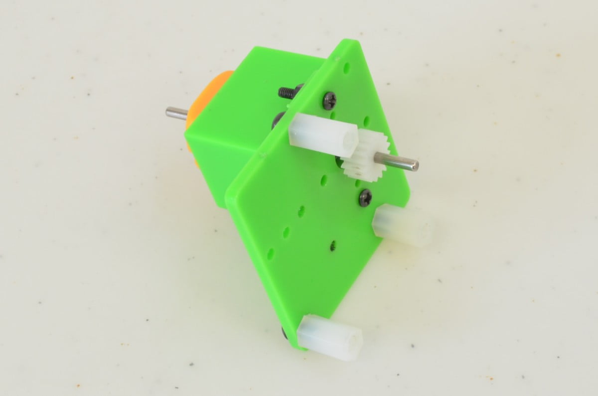
Step 5 – Attach the Standoffs
Next, we will attach the three nylon standoffs to the first gearbox panel. These are what keep everything lined up and spaced out correctly. Using three of the larger screws, attach each nylon standoff to their corresponding point on the panel. The remaining three large screws will be used to hold the other panel in place once we have assembled the gearbox – so put them somewhere safe!
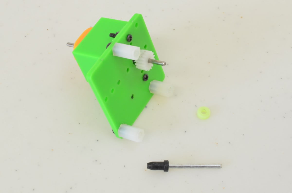
Step 6 – Intermediate Shaft
The next thing we need to add is the intermediate shaft, this is a small shaft with a double gear that meshes between the motor shaft and the handle shaft. This one needs a few small parts, so take a careful look at the pictures below and ensure you have it set up correctly:
Find the small shaft, a small plastic spacer, and the black end cap
Press the end cap onto the shaft
Insert the shaft into the hole and add the spacer as shown
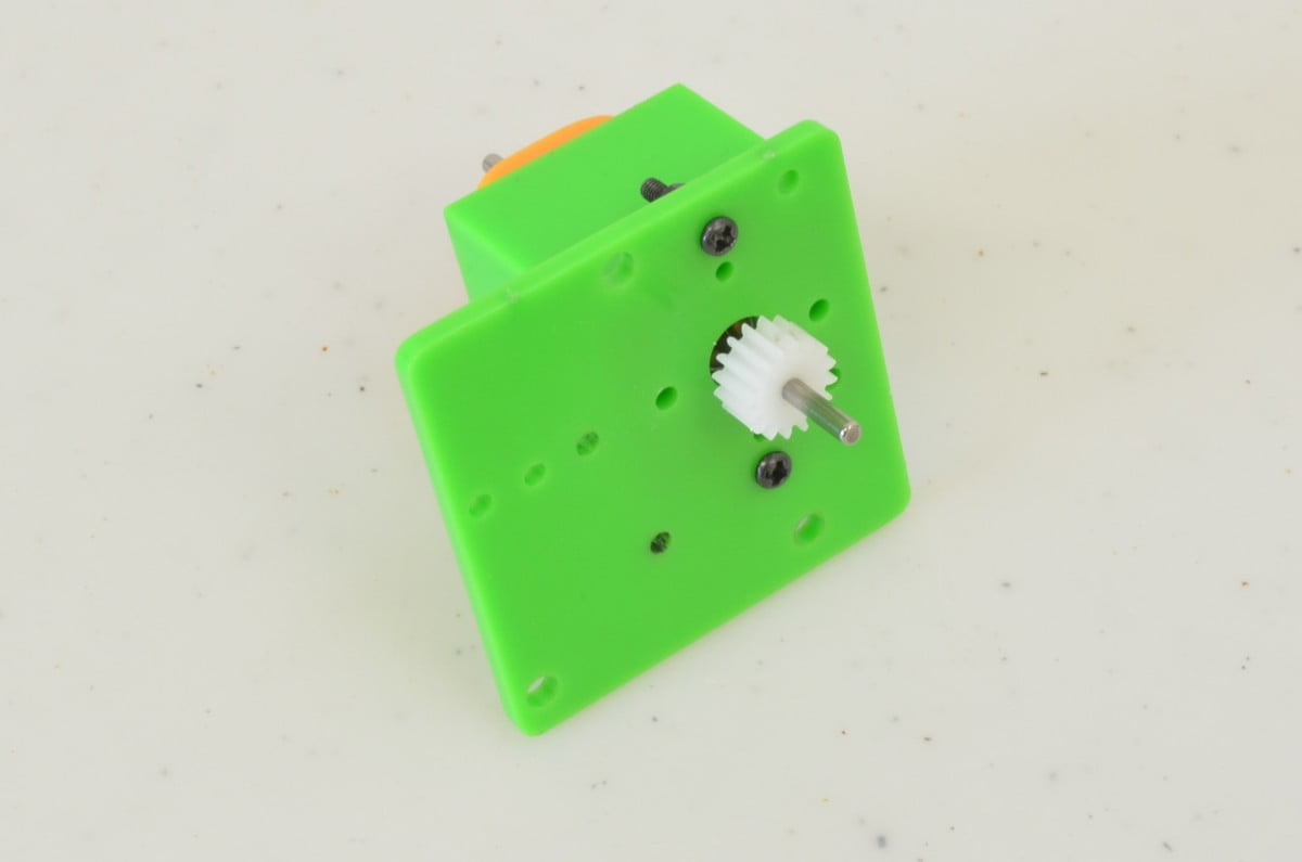
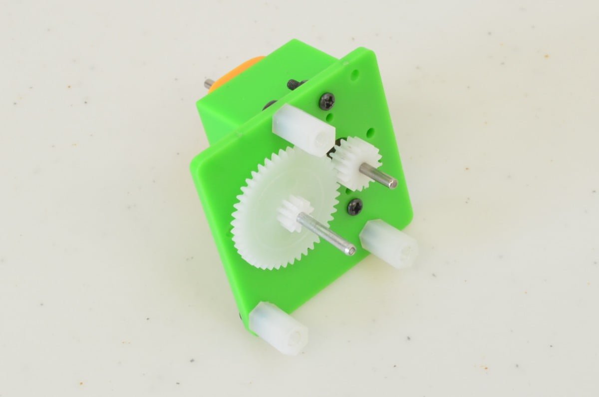
Step 7 – Intermediate Shaft Gear
The intermediate shaft gets a gear as well, this is the lose gear from the package. We are going to press it onto the shaft carefully as shown. Be sure to put this gear on the correct way!
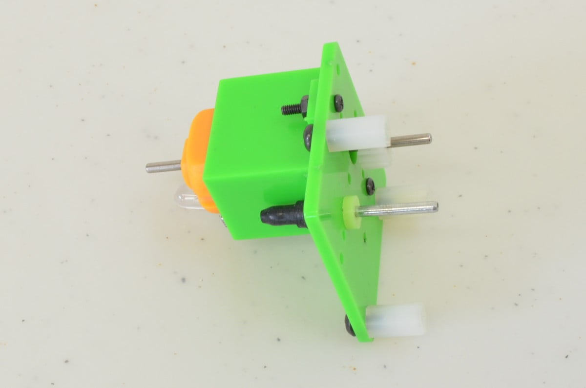
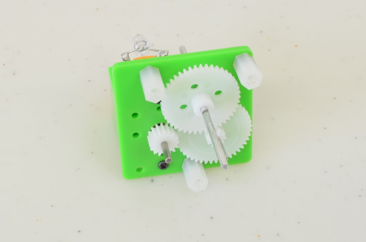
Step 8 – Handle Shaft
Next, we need to add the shaft and gear that the handle will be attached to. This is the long shaft with gear in the middle. When it is slid into the gearbox panel, it should mesh with the intermediate shaft gear as shown in the second photo.
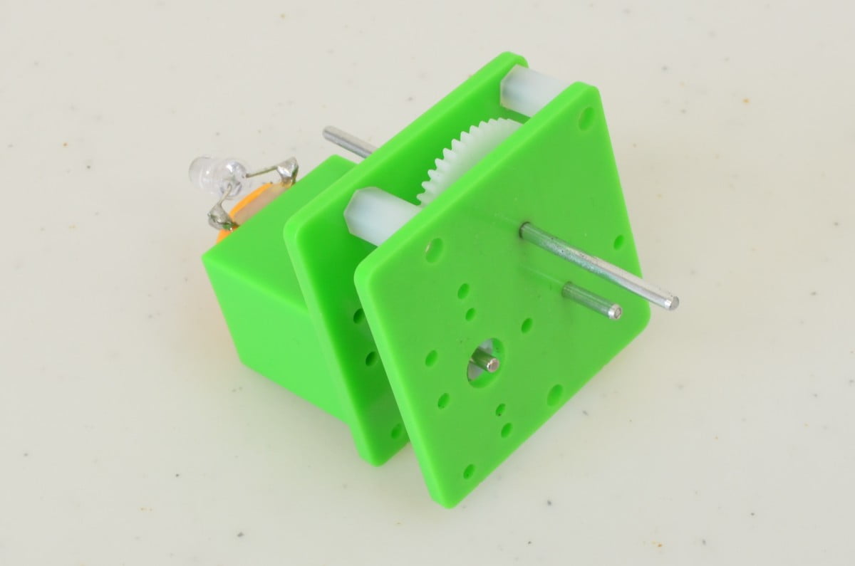
Step 9 – Gearbox Panel
Now that the gearbox is completed, we can add the other panel. Just make sure everything lines up and slide it onto the shafts. The Intermediate shaft gets another one of the end caps added as shown.
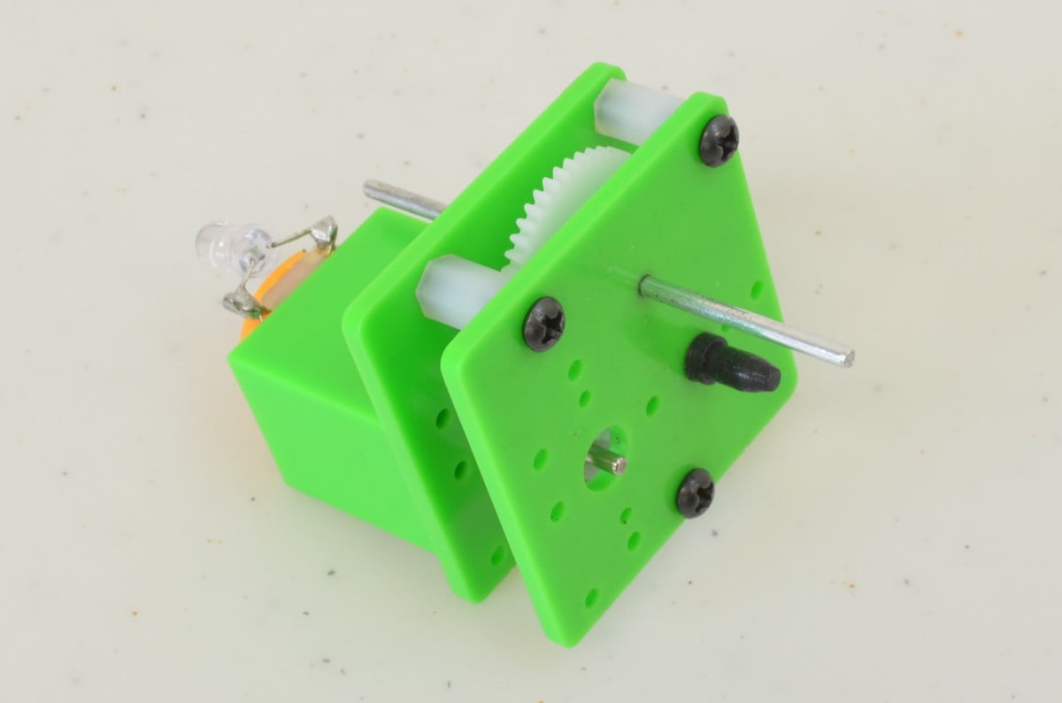
Step 10 – Gearbox Panel Part II
We can now use the last three screws to attach the panel to the gearbox.
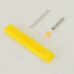
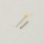
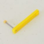
Step 11 – Gearbox Handle
The gearbox handle is made up of the yellow arm, a short metal shaft, a short metal tube, and another plastic spacer (that acts as an end stop). We are going to start by adding the end stop to the short metal shaft, and then slide the metal tube over the metal shaft. Once this is done, the assembly can be pressed into the yellow arm as shown.
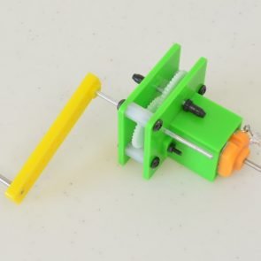
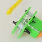
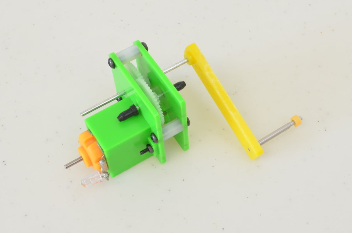
Step 12 – All Done
And with that, it is completed – give it a spin and see what happens. The direction you spin it to get it to light up is dependant on which direction the LED was attached, so be sure to try spinning it both ways!
[info]Have A Question?
If you have any questions, or need further clarification please post in the comments section below; this way future users of this tutorial can see the questions and answers!
[/info]